In progress
Mars Society science electrical module
Electrical design for HURC's life-detection and surface-sampling science payload: sensor interfaces, actuator drive, and power integration with the PDB rails above.
Harvard ’29 Electrical Engineering
I'm a sophomore at Harvard College studying Electrical Engineering. I design power systems and the PCBs that control them.
KiCad · Altium Designer · EasyEDA · Fusion 360 · C · ESP32 · Teensy · ATtiny

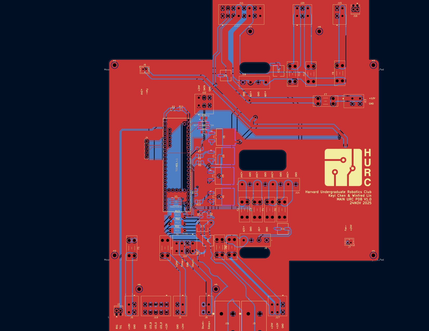
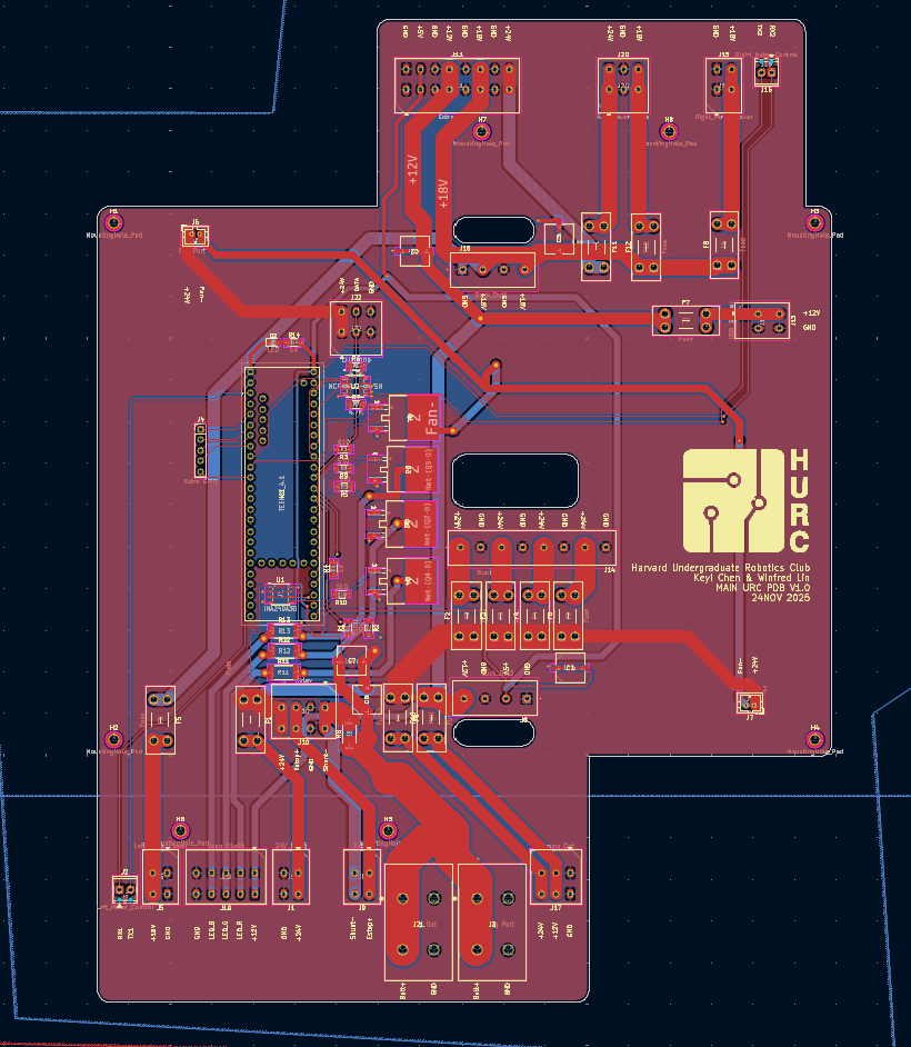
Outcome. A fully functioning central power distribution system for the Harvard Rover, which operated successfully through the University Rover Challenge SAR video report. It converts a 25.6 V, 50 A battery input into 24, 18, 12, 5, and 3.3 V output ports, so each subsystem can easily draw the voltage it needs.
My contribution. I co-designed the board with Winfred Lin. On the power side, I laid out the buck converter input and output ports, worked out how power is distributed across the ports, and placed the components. I added fuses and filter capacitors to protect the outputs and brought out power for the fans and the Teensy's GPIO. For battery management, I designed the E-stop relay circuit and the monitoring: a shunt resistor for current and a voltage divider for voltage, each read by its own sensing IC.
Skills applied. KiCad, PCB schematic design, trace calculations and layout, power distribution and protection, current and voltage sensing, MOSFET switching, mechanical integration, assembly, and bench verification.
Motivation. When I joined the team, the Rover's electrical system was a row of WAGO connectors with no capacitor filtering or battery monitoring. We spent a semester designing, iterating on, and manufacturing the first comprehensive board, one that adapts to each subteam's changing requirements while safely powering the Rover.


Outcome. About 15 new members produced their first PCB in one semester, taught from their first schematic all the way to a fabricated board. The program also produced the team's Rover-wide electrical architecture schematics.
My contribution. I designed a smart fidget spinner PCB as the teaching vehicle: a USB-C input, MCP73831 LiPo charge management, an AP2112K 3.3 V LDO, an ATtiny1614 programmed over UPDI, a LIS3DH accelerometer, and four addressable LEDs, routed on two layers around a bearing cutout. The boards were fabricated at JLCPCB, and assembly is the next stage. I also wrote the curriculum, recorded the guide videos, and taught the sessions.
Skills applied. Mixed-signal PCB design, Li-ion charge management, LDO regulation, small-MCU firmware, I²C sensors, constrained routing, and teaching.
Motivation. New members were arriving with no hardware background and nothing to practice on. One small board that contains every subsystem a Rover board needs lets them complete the full design-to-fabrication loop before they touch Rover hardware.
 Guide: a simple LDO regulator stageRecorded training session. Watch on YouTube.


Outcome. A two-wheeled, single-axis inverted pendulum that uses PID control to balance and recover from disturbances. It was built in two weeks for under $99. Harvard's Area Chair for Electrical Engineering requested the project report as a lab for her upper-level controls course.
My contribution. I designed the circuit and hand-soldered it onto protoboard. I wrote the control firmware, including a complementary filter (0.95 gyro / 0.05 accel), startup calibration, and PID with a clamped integral and derivative dead zone, and set up over-the-air (OTA) uploads for fast tuning. After an overcurrent destroyed a motor driver, I added 2 A fuse protection; v2 runs on LiPo with that protection. Chassis CAD was by Evie Eyers and Nicholas Bondar.
Skills applied. Sensor fusion, PID tuning, ESP32 firmware with OTA, I²C IMU configuration, H-bridge motor drive, power budgeting, and overcurrent protection.
Motivation. The inverted pendulum is the canonical unstable system. I wanted to build the full loop, sensor to actuator, on cheap hardware instead of a kit.


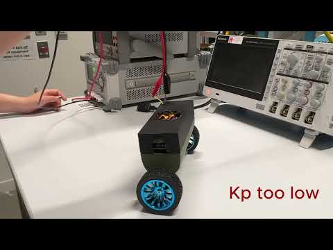 Watch it balanceProject video. Watch on YouTube.


Outcome. A single integrated module for monitoring Lake Bardawil, Egypt, built for a group of environmental scientists. It measures salinity, temperature, depth, and water chemistry, and was tested successfully in the Charles River. Because the project is open source, we tested and documented many low-cost sensing methods to find the ones that are cheap and still reliable, so others can reproduce the build. We presented the work to researchers at the Woods Hole Oceanographic Institution (WHOI).
My contribution. I integrated the subsystems, consolidating every sensor and actuator onto one board. I designed the schematic and layout in EasyEDA, then milled, drilled, and hand-soldered the board. My research focused on the depth sensor: I wrote firmware that adapts a sensor rated only for air to shallow-water use.
Skills applied. EasyEDA, CNC PCB milling and hand assembly, 4-electrode AC conductivity sensing with thermistor compensation, UART sensors, L9110S pump drive, ESP32-S3 firmware, and field testing.
Motivation. Twelve students were selected from about 100 applicants for Nathan Melenbrink's Machine Ecology seminar to build an open-source tool for a real restoration project. A collection of separate sensor breakout boards cannot be deployed in the field, so the whole system needed to live on a single board.


In progress
Electrical design for HURC's life-detection and surface-sampling science payload: sensor interfaces, actuator drive, and power integration with the PDB rails above.
2026
Instead of buying the recommended distribution board, I re-architected the power electronics for an existing open quadruped design running on a 7.4 V LiPo, adding input capacitance and protection the original lacked. A quick study in picking up someone else's design and making it safer. Original design by Dorian Todd.
Fall 2025
Modified HC-SR04 ultrasonic sensors to triangulate a user's position, driving an autonomous follow-me bag for students with mobility injuries.
Harvard ’29, Electrical Engineering. Embedded systems and power electronics. Electrical Training Lead for the Harvard Undergraduate Robotics Club's Rover team; designed its power distribution board.
Previously captain of FIRST Robotics Team 8267 (Long Beach, NY); engineering intern at TTM Technologies / Telephonics; operations intern at the City of Long Beach water purification plant.
Open to electrical engineering internships in embedded systems, power electronics, and hardware design.